
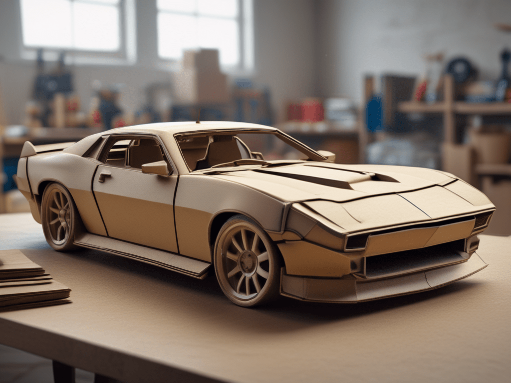
Often the most overwhelming part of fabrication is deciding where to start. Are you going to model your part using scrap material you have laying around? Perhaps you’re going to start with measurements and jump right into 3D modeling on your computer? There’s no wrong answer, but getting started is the fabrication equivalent of writer’s block. We’ve all started down one path with an idea only to scrap the existing design and start anew, but failure at this stage is ok and can lead to improvements in your second or third (or tenth!) designs. Start low cost and keep things simple with CAD… Cardboard Aided Design.
The rules are simple – grab some scrap cardboard, a knife, tape, and whatever else you might need to turn your idea into reality. Use this time to make changes, refine your idea, and hone your project in without making a costly mistake. Make your splitter or your intercooler ducting, your spoiler or your accessories mounts. Now is the time to screw it up and start over until you’ve got something you like.
Getting Started with CAD
Like all fabricated parts, the wing story begins with an idea (and a Voltex Type 7 GT wing). In 2017, application-specific chassis mounted wing options were not prevalent like they are today today where there are a number of direct-fit options available. (though the fabricator reading this doesn’t want direct-fit, they want to make something!). This lack of options forced some ingenuity to create something unique and, of course, something that fit. With a Bachelors Degree in Cardboard Aided Design under the belt, the first step was obvious… create an idea from cardboard.
After some rough sketches and test-fitments, Version 1 was born… and it was ugly. Though the test fitments worked and it would seemingly do the job, the look left much to be desired, so it was back to the drawing board. Following some further pencilwork, Version 2 hit the streets with a whole new lease on life (as they say, first is the worst and second is the best – something that seems to ring true in fabrication). The freshly minted and CAD’d product was spray painted black to further test the look and it passed with flying colors. Now what?
CAD’s Big Brother: MDF (Medium-Density Fabrication)
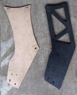
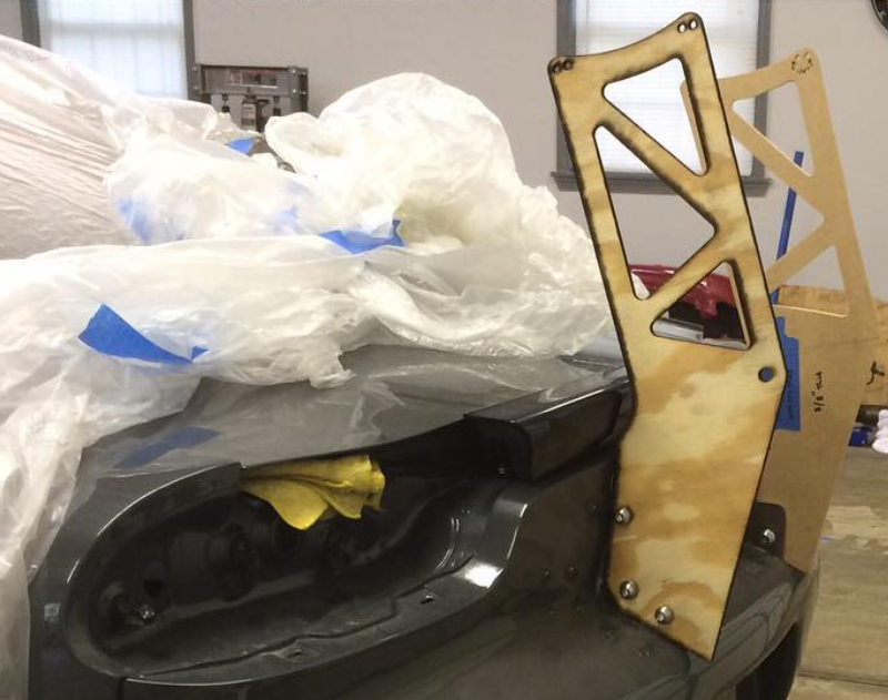
With a completed CAD “prototype” it was time to send in the big guns. Enter MDF. The transfer was easy – the cardboard template was overlaid on 1/2″ MDF board and traced with a Sharpie. Final cuts were made with a jigsaw and smoothed out using a Dremel followed by a short stack of sandpaper. The result looked the part and could hold the weight of the wing, a success on all fronts.
With one stand complete and refined, a second (and less detailed) piece was made to be able to fully mock the wing up. Some small adjustments were needed, but both pieces held, so it was back to the flow chart:
- Idea to CAD
- CAD to MDF
- MDF to ???
In creating something like this, if you don’t have the right tools, finding other resources is key. For this particular project, and without the tools to cut the necessary thickness aluminum, there was nowhere else to go but contact an expert. Lucky for me, this expert happened to be a buddy’s father who worked in the engineering department of a nearby pharmaceutical company, but for anyone needing this type of service, seek out a company/contact with a CNC Mill/Router or a Waterjet.
CAD (…but for real this time)
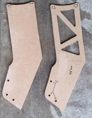
The MDF template was left with the expert who quickly got to work by taking measurements and creating a true 3D CAD file in Solidworks based on the information.
*For those wanting to tackle this on their own, SketchUp offers a free basic version of their modeling program. The browser-based Sketchup program is an entry-level way to get into 3D modeling, not just for projects like this, but for 3D printing as well.
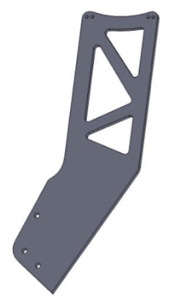
The completed 3D file was ultimately used to create a cutting path for a CNC laser cutter that cut a new wooden template of the wing stands. This template was dropped back off to test fit one final time and ensure the measurements and CAD file needed no further adjustments.
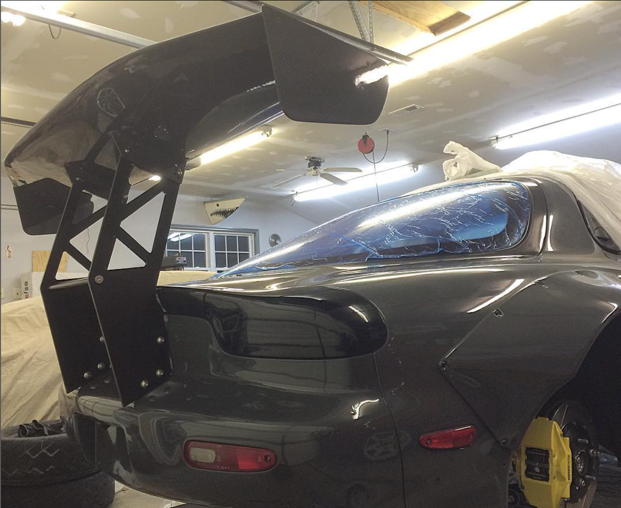
With fitment exactly as intended (a testament to the experts drafting abilities) the green light was given to given to cut the final product out of 5/8″ aluminum. Since my buddy’s father did not have access to the machinery required to cut this thickness aluminum, the file was handed over to a friend of his who worked at a local tech school (resources, remember?)and the rest was history. The final pieces were delivered back in raw aluminum and dropped off at a nearby powdercoating facility to finish with a satin black coating. A week later, the project was mounted back on the car and the project was deemed a success. Mission complete.
![[VIDEO] 3D Scanning a CrossKart](https://fabricatorsdomain.com/wp-content/uploads/2025/02/fs-sxms_airbox_thumbnail.png?w=1024)

Leave a comment